Pacemaker Hardware Reference Platform Details
From Computing and Software Wiki
Contents |
Pacemaker Hardware Reference Platform Details
Introduction
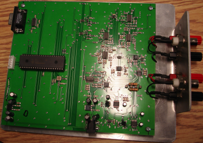
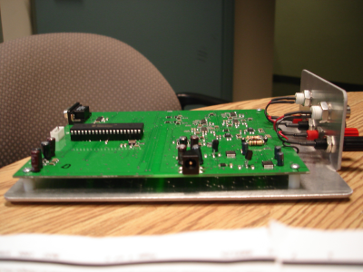
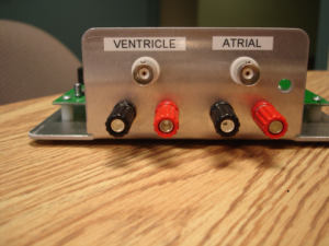
Here are some photos of the prototype hardware reference platform that we have produced.
The side photo show the standard 2mm power jack. A 9-12V adapter providing 300mA should suffice. You can even run the board off of a 9V battery for some time .
The next photo shows the BNC and binding post connectors that we have put on so allow the boards to be easily connected to a PC running Labview or some other software to simulate a heart and facilitate testing and debugging.
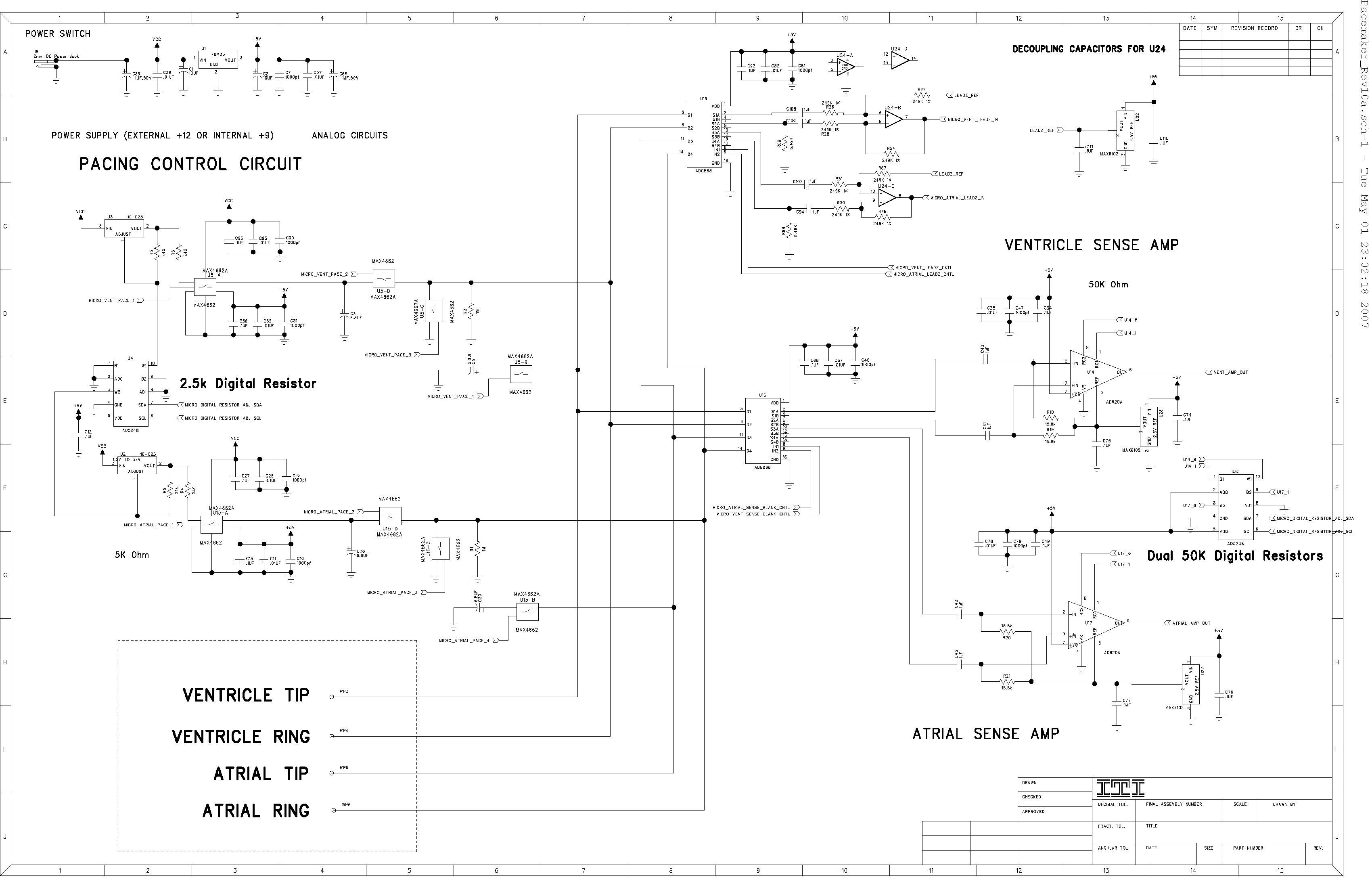
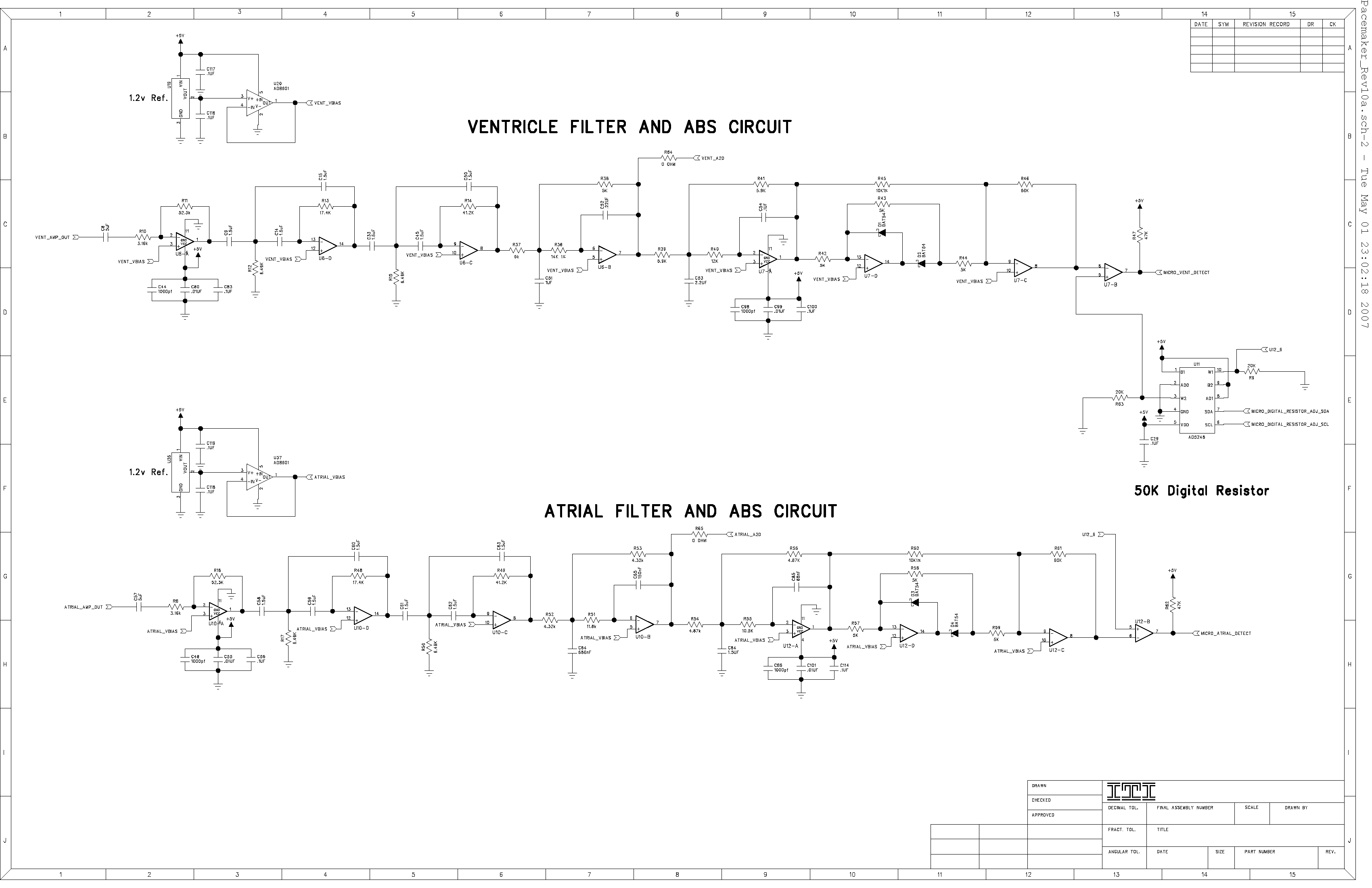
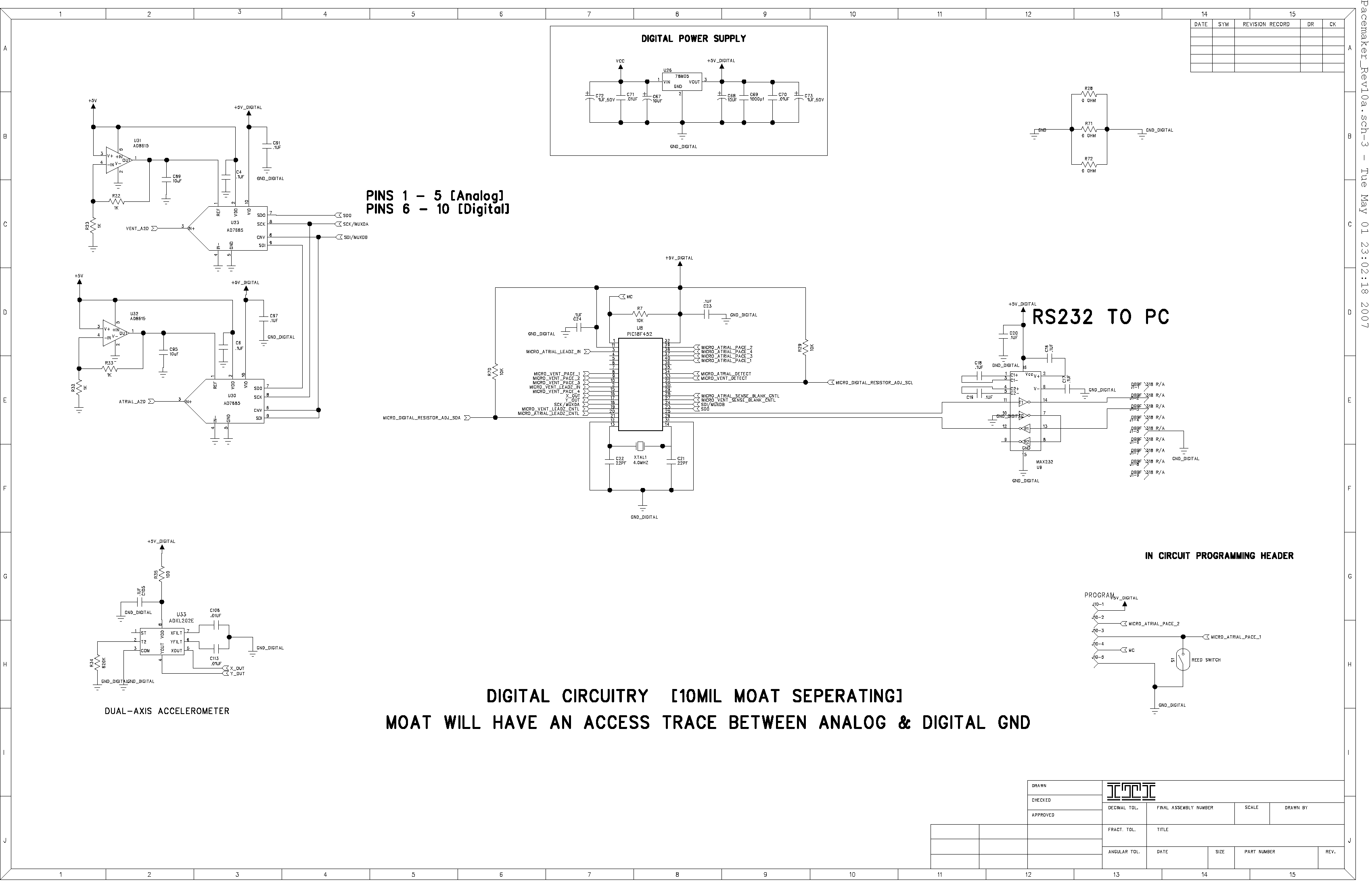
Here is the originial design of the Pacemaker Hardware Reference Platform.
Bill Of Materials (BOM)
We will be releasing the Bill Of Materials (BOM) and the schematics for the hardware once the design is finalized so that you can also produce your own boards if you would prefer to do that.
| Qty | Reference | Description | MFR PART NUMBER | MFR | DIGI-KEY PART # | COST <1000 | Total Cost $ |
| 4 | C1-2 C67 C68 | CAP 10UF 25V ELECT PW RADIAL | UVX1H100M | NICHICON AMERICA | UPW1E100MDH-ND | $0.07 | $0.26 |
| 13 | C14-15 C33 C45 C50 C9 C58-63 C84 | CAP 1.5UF 10V CERAMIC X7R 1206 | ECJ-3YB1A155K | Panasonic - ECG | PCC1867CT-ND | $0.29 | $3.72 |
| More | To | Come |
