Designing a Small Business Intranet
From Computing and Software Wiki
Based on a set of network requirements for a small business I have created an intranet to satisfy the businesses specifications. The network design utilizes a private address space, layer 2 switches, layer 3 routing switches and firewalls. I will describe several design aspects of the network including the wiring design, IP addressing design, redundancy design and the Internet network design.
Contents |
Business Specifications and Requirements
- Company X is moving into a new three floor building.
- Four hundred users will work in this new location.
- A computer room will be built on the 1st floor to house servers.
- There is currently no data communication cabling in the site.
The business requires a private Intranet design to support the following requirements:
- Twenty servers in the computer room (all applications are TCP)
- Redundant network within the building (redundant NIC’s in the servers)
- Very high speed access to all users PC’s to support data transfers of terabits of information between users.
- Very scalable network.
- Printers on each floor.
- Outbound Internet access for users.
- Inbound Internet access to a couple Web servers.
Wiring Design
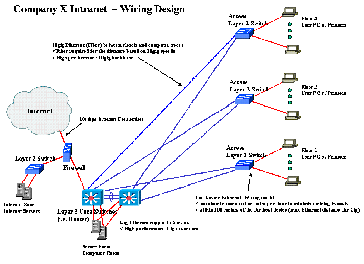
While creating a wiring design to meet businesses specific network requirements both cost and performance were the main concerns. It was important to ensure the most cost effective wiring design which would support the very high speed network access required for data transfers of terabits of information across the network.
Gigabit Ethernet wiring (cat 6) will be run to each user on the network (PC’s, printers). Category 6 is a high quality cable with low attenuation (loss of signal strength as it travels the length of the cable) with a maximum length of 100m. On each floor all end device Ethernet wiring will be run to a single concentration point (a closet). This Category 6 Ethernet cable minimizes the wiring and cost of the network.
Between the closets and computer room 10gig Ethernet (Fiber) will be run. Ethernet fiber is required the traverse the potentially larger distance between each floors’ closet and the computer room. This provides a high performance 10 gig network backbone.
To connect the servers and layer 3 core switches Gig Ethernet wiring (cat 6) will be run. This Gig Ethernet wiring will again minimize the cost of cable in the network.
The Internet connection will utilize a 10mpbs Ethernet wiring. This wiring is very cost effective and is more then enough for this connection.
IP Addressing Design
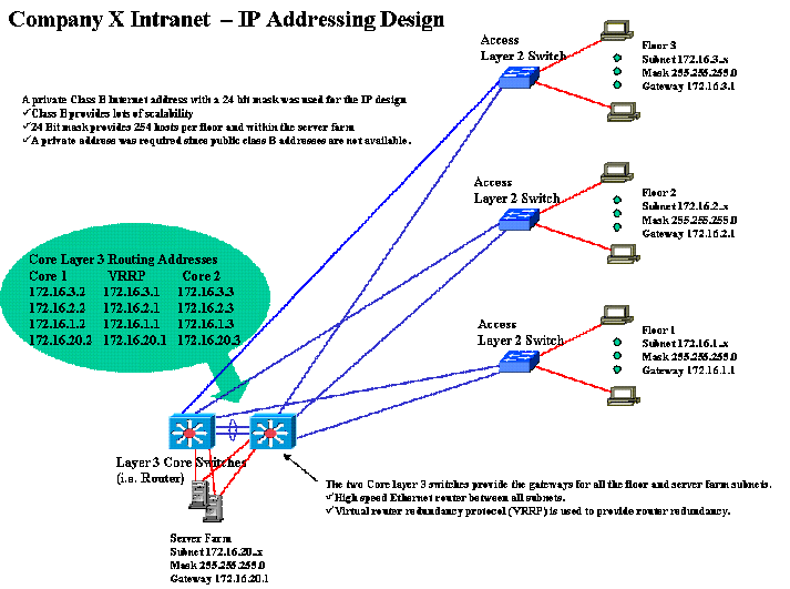
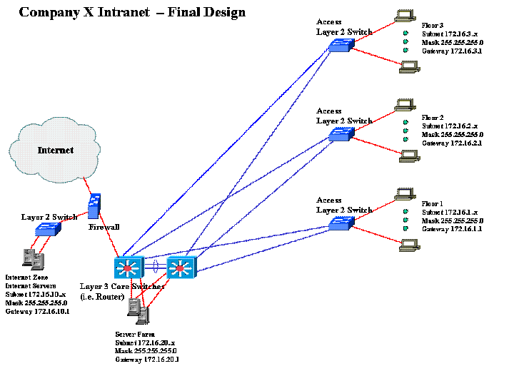
For Company X’s Intranet design a private Class B Internet address with a 24 bit mask was used. This design provides more then enough IP address to meet the company’s requirements and provides a lot of scalability and will be able to handle company growth. The 24 bit mask provides 254 hosts per floor and within the server farm. A private Internet address was required because public class B addresses are not available. The IP addressing diagrams also show the routing addresses for the two Layer 3 Core Switches including the virtual router gateway addresses.
Internet Design
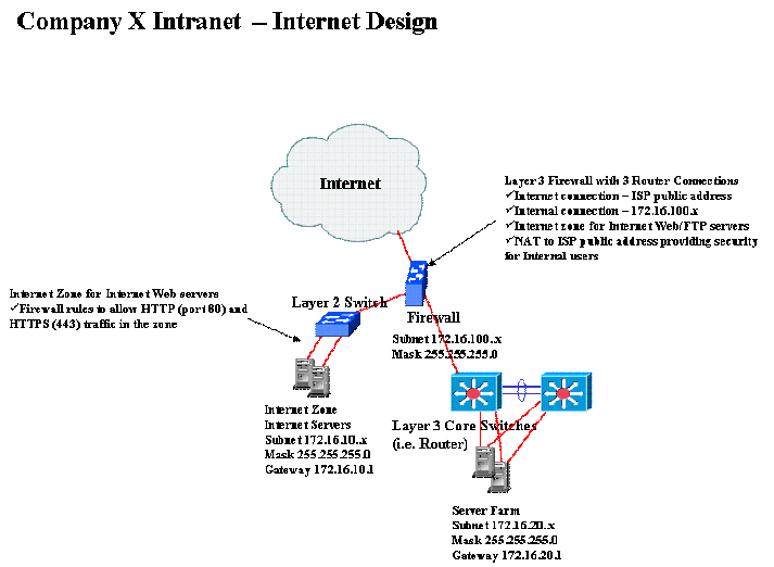
I created a secure internet zone to place the Internet servers in order to isolate them and place rules on the firewall to allow inbound internet access only to the internet zone.
Outbound traffic is NATted (Network Address Translation) by the firewall between the internal private IP address space and the public IP address space of the Internet Service Provider. The outbound NATting also provides an extra level of security since the private IP addresses are hidden from the internet.
Redundancy Design
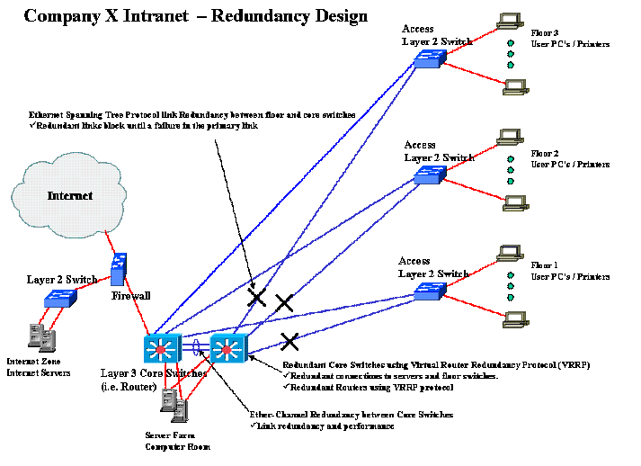
The two purposes of creating a redundant network design are reliability and performance. Network reliability refers to a networks ability to provide communication in the event of network hardware failure, while network performance refers to the networks quality of service. In Company X’s network design there are three separate redundancy features:
Redundant core switches using Virtual Router Redundancy Protocol (VRRP)
One router acts as the master router and will control all network communications while the other backup router remains idle until needed. If the master router experiences failure the backup router will take over and continue network communication. The Virtual Router Redundancy Protocol is used to determine which VRRP router is currently in use. VRRP will advertise a default gateway for a virtual router, and dynamically assign the responsibilities of the virtual router to a network router. The use of two routers and the VRRP ensure network reliability in the event of a hardware failure.
Ethernet Spanning Tree Protocol link Redundancy between Layer 2 and Layer 3 Switches
Each layer 2 switch is physically connected to both layer 3 core switches (routers). For a network to operate properly there can only be one active path between the each device, eliminating loops from the network. Spanning-Tree Protocol will block a redundant link until a failure occurs in the primary link. When a failure occurs the Spanning-Tree Protocol will activate the redundant link after reconfiguring the spanning-tree topology. These redundant links provide a backup for the active links in the network. These redundant links provide network reliability in the case of link or hardware failure.
Ether-Channel Redundancy between Core Switches
An Ether-Channel is created between the layer 3 core switches. Ether-Channels allow for several Ethernet physical links to be grouped together and represented by a single logical Ethernet link. If a link inside an Ether-Channel fails, all communications over that link will be taken over by the remaining links. Ether-Channels provide increased network performance since each physical link between the Core Switches can be used. They also provide increased network reliability in the case of a link failure between Layer 3 Core Switches.
Conclusion
The following diagram is the final design of Company X’s network. The network is scaleable Class B private network that provides very high speed access to all users PC's to support data transfers of terabits of information between users. The network allows outbound Internet access for users and inbound Internet access to a pair of Web Servers.
References
1. Network Address Translation, http://en.wikipedia.org/wiki/Network_address_translation
2.Virtual Router Redundancy Protocol, http://en.wikipedia.org/wiki/Virtual_Router_Redundancy_Protocol
3. Spanning Tree Protocol, http://en.wikipedia.org/wiki/Spanning_tree_protocol
4. EtherChannel Introduction, http://www.cisco.com/en/US/tech/tk389/tk213/tsd_technology_support_protocol_home.html
5. Category 6 Cable, http://en.wikipedia.org/wiki/Category_6_cable
See Also
Wireless Network Security
Semantic Web
SOA enhancements through XML Networking
Transport Layer Security
External Links
--Davisml3 17:40, 9 April 2008 (EDT)
