Cell BE - A Network on a Chip
From Computing and Software Wiki
Network on a chip (NOC) is a paradigm in the design of parallel hardware architecture. It differs from System on a chip (SOC) by featuring generic communication channels between processor elements instead of specialized buses to simplify chip design. Network on a chip systems have the ability to have processing elements operating on different data elements simultaneously without special framework. These characteristics allow better energy-performance characteristics[1].
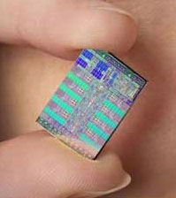
The Cell Broadband Engine (Cell BE) is a network on a chip design in production by Sony, Toshiba and IBM (STI). The Cell BE demonstrates these characteristics in a high performance, scalable production architecture.
Contents |
Cell BE Architecture
Information in this section is taken information distributed in the IBM Cell BE SDK and available from [2].
The Cell BE is a [SIMD] architecture which operates as a network on a chip. The individual elements communicate with one another exclusively over a interconnect network which operates in a manner comparable to a token ring network. The elements operate by sending device service requests and responses to one another.
Processors
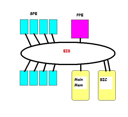
The Cell BE is comprised on 2 primary processor types; 1 Power PC Element and 8 Synergistic Processing Elements.
Power PC Element
The Power PC Element (PPE) is a 64 bit processor responsible for running operating system functions. The PPE controls thread level parallelism, and acts as a controller for the Synergistic Processing Elements (SPEs). It supports vectorized single precision floating point operations, and IBM's quad-precision (long double) floating point format. The PPE is responsible for memory address translations between the SPEs and main memory.
Synergistic Processing Element
The Synergistic Processing Element (SPE) is the main computational engine for the Cell BE. The SPE is highly optimized for floating point operations. The SPEs are capable of performing a single memory instruction and a single data operation every cycle. It is important to remember that the SPE cannot directly access main memory and must request data by a request through the PPE due to memory address translations. The SPE contains 256kB of local store memory where a copy of the data is kept. This local store is not accessible by elements other than the SPE it resides on. The implication of this configuration is that once sufficient data is queued, computation can begin in step with memory transfers. Although there is an initial penalty it is quickly overcome for computations on large data sets. It is also the programmer's responsibility to ensure data synchronization is handled appropriately. Each SPE may initiate up to 16 memory requests (inbound or outbound data movement) simultaneously.
Controllers
Element Interconnect Bus
The Element Interconnect Bus (EIB) connects the various elements of the Cell BE to one another. It operates in a manner similar to a high bandwidth token ring network. Communication between elements is performed in packets of 16B, each element potentially receiving 1 packet each cycle.
Memory Interconnect Controller
The Memory Interconnect Controller (MIC) interfaces directly with the main memory of the system. It receives memory access requests from the PPE and SPEs via the EIB and returns data to the processors in packets via the EIB.
Bus Interface Controller
The Bus Interface Controller (BIC) is a configurable network interface. It is a Rambus FlexIO card that treats the EIB as a transport layer of a network. It has 2 physical interfaces to the EIB and maps those interfaces to a physical network connection. A common use of this interface is to pair with another Cell BE, thus creating a network of 2 PPEs and 16 SPEs. Memory address translation is handled by the BIC allowing processors on one physical chip to make a memory request to the MIC of the second physical chip. In super-computer systems, this interface is usually connected to a backbone which in turn manages clusters of Cell BEs.
Network on a Chip
Traditional chip design (system on a chip) has focused on overcoming the [memory], heat dissipation issues and other physical limitations. As multi-core approaches have gained in popularity, communication complexity has necessarily increased, occupying more of the available resources. Additionally power consumption versus performance is becoming increasingly important both for commercial and environmental reasons. Network on a chip is a design approach that attempts to avoid complicated communication scenarios by drawing on existing network structures and theories. One key feature of this simplification is that dedicated interconnect buses (such as a memory bus) are removed in favour of a generalized communication channel. Component designs are only restricted in that they must have an interface to the communication channel. Specific network topologies and protocols can be applied to particular chip designs with a well established knowledge of the advantages and limitations.
Single Cell BE Example
Scenario: 1 PPE, 8 SPE configuration, operating system loaded and running on multiple threads on the PPE.
    User program is started on a thread by the PPE.
    The user program sets up initial values (stored in the PPE registers) which are then send to memory over the EIB.
    The user program initializes threads to start computational programs on the SPEs.  Note, there is no requirement that all SPEs run the same program.
    I/O requests are sent over the EIB to the SPEs, transferring the executable code, which then begins to execute.
    SPEs begin to make memory requests to the PPE, which are translated and retransmitted to the memory controller.
    The MIC initiates a memory transfer to the requesting SPE.
    The SPE begins computation on the received data.
    If an SPE needs data that is on another SPE, a SPE to SPE memory transfer request can be initiated over the EIB.
    If an SPE needs to send a mailbox message, an event signal or raise an interrupt on the PPE, it can initiate SPE->EIB->PPE messages.
    As data completes, it can be transferred back to main memory from the SPE->EIB->PPE->EIB->MIC.
Clearly, the number of communication requests are quite high with 8 SPEs running in parallel. Traditional chip designs have excelled at creating pathways between components, here we would probably add pathways from memory to each SPE to facilitate movement. This would create a large number of pathways, especially when inter-SPE communications are allowed. By having a general channel this complication is removed. Also, suppose a single SPE is performing a low computational cost, data intensive operation. Suppose also that the other SPEs are either idle, or performing high computational cost, low data access operations. In the SOC design, many pathways are inactive. In the NOC design, the single SPE is able to take advantage of the extra bandwidth access.
Dual Cell BE Example
Scenario: 2 Single Cell BE chips, communicating over the BIC on a common, problem with a large data set (such as a hydrodynamic simulation)
    Assume that each of the Cell BE chips is operating in a manner described in the previous example.
    An SPE on the first Cell chip issues a memory request for a block of memory connected to the second Cell chip via the EIB to the PPE on the first chip.
    The PPE performs a memory address translation and recognizes it is a network resource, it then issues a network memory request PPE->EIB->BIC.
    The request follows BIC1->BIC2->EIB->MIC to the second Cell chip.  The data now returns via MIC->EIB->BIC2->BIC1->EIB->SPE.
    It is possible for SPEs on one Cell in this configuration to make messages to the PPE or SPEs on the other Cell in a similar fashion.
Here we see that the architecture is scalable. The penalty associated with the communication BIC1->BIC2 has no impact on system performance as the BIC is faster than the EIB.
Cluster Configuration Example
Scenario: Many Cell BE chips connected over an external backbone to one another via their respective BICs.
In this scenario, everything stated about the Dual Cell BE example applies. There is additional complexity and the backbone usually uses it's own processor to provide network address translations, or implement a higher level communication protocol. Additionally the backbone speed needs to be sufficient that requests from the extreme ends of the network continues to exceed the speed of the EIB.
This configuration is similar to the one that was used to create IBM'Roadrunner. Roadrunner is listed in the #1 spot on the LINPACK TOP500 list, and the first to run with a sustained speed in excess of a petaflop[3].
Network Security Implementation
The PlayStation 3 (PS3) was designed to use a Cell processor. The design reserves 2 SPEs as private; one is disabled to increase production yields and the other is reserved for the PS3 operating system. The decision to reserve a SPE for the operating system was largely for system security. In the PS2, users were able to create illegal copies of software and bypass the built in copy protection mechanisms by installing their own processor, a [mod chip]. The PS3's reserved security SPE can be seen as a network security device, that monitors the integrity of the system.
References
[1]http://en.wikipedia.org/wiki/Network_On_Chip
[2]http://www.research.ibm.com/people/m/mikeg/papers/2006_ieeemicro.pdf
[3]http://www.lanl.gov/roadrunner/
See Also
External Links
- System on a Chip Wikipedia Article
- IBM developerWorks Cell Broadband Engine Resource Center
- PlayStation 3 Home
--Adamssw 23:34, 12 April 2009 (EDT)


